How to Measure Old Damaged Slewing Bearing for Accurate Replacement
Slewing bearings (slewing rings) cannot be directly matched by appearance alone after damage, wear, deformation or part loss. Complete dimension measurement + structural parameter recording ensures the new replacement bearing fits perfectly without reworking the mounting base. The full measurement steps are sorted below, divided into core dimensional measurements, structural feature checks, accessory data recording and verification notes.

1. Pre-Measurement Preparation
Clean the bearing thoroughly: Remove grease, rust, mud, metal debris and seal fragments from raceways, mounting holes, inner/outer rings and tooth surfaces; expose complete machining surfaces for accurate caliper/micrometer measurement.
Check deformation: Tap the ring with a rubber mallet to check for obvious bending, warping or crack expansion; record visible damage location (inner ring crack, tooth breakage, seal failure, ball/roller loss).
Prepare tools: Vernier caliper, outside micrometer, tape measure, depth gauge, protractor, thread gauge, marking pen, camera (take full photos of front, side, tooth face and mounting hole layout).
2. Core Key Dimension Measurement (Most Critical)
2.1 Outer Ring & Inner Ring Overall Dimensions
| Parameter | Measurement Method | Purpose |
|---|---|---|
| Outer diameter (OD) of outer ring | Measure maximum outer circle with tape/caliper (2–3 positions averaged to avoid oval deformation) | Confirm overall outer boundary size |
| Inner diameter (ID) of inner ring | Measure minimum inner hole of inner ring | Fit with equipment rotating shaft/pivot journal |
| Bearing total height (H) | Measure axial thickness at 4 evenly spaced points | Match equipment axial installation clearance |
| Outer ring inner bore diameter | Measure inner hole of outer ring (raceway outer positioning size) | Locate outer ring mounting shoulder |
| Inner ring outer diameter | Measure outer circle of inner ring | Locate inner ring positioning shoulder |
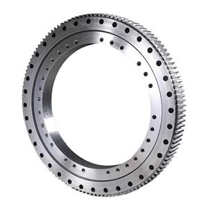
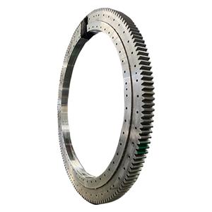
2.2 Mounting Hole Parameters (Cannot Be Ignored)
Hole layout: Count total mounting holes on inner ring and outer ring separately; mark hole distribution (equally spaced / unequal spacing).
Hole pitch circle diameter (PCD): Measure the circle diameter passing through the center of all mounting bolt holes; measure crosswise twice for average value.
Single hole size: Measure hole diameter, counterbore depth and counterbore diameter; use thread gauge to confirm bolt thread specification (M12/M16/M20 etc.), through hole or tapped blind hole.
Hole edge margin: Distance from mounting hole center to ring outer/inner edge, to avoid new bearing hole misalignment.

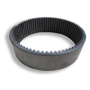
2.3 Gear Tooth Parameters (Toothed Slewing Bearing Only)
Two common types: external gear teeth (outer ring with teeth) / internal gear teeth (inner ring with teeth) Number of teeth (z): Direct count of complete intact teeth (exclude broken/missing damaged teeth).
Module (m): Standard calculation formula: Pitch circle diameter (Dp) = Module × Tooth number → m = Dp / z
Measure tooth pitch circle diameter accurately with caliper, then calculate module.
Tooth height, tooth addendum, tooth root diameter: Measure to check tooth wear limit; record tooth pressure angle (standard 20° for most engineering machinery).
Tooth width: Axial length of the meshing tooth surface.
2.4 Raceway & Rolling Element Data
Raceway structure: Single-row ball / double-row ball / three-row roller / cross roller slewing bearing (judge by disassembling partial seal or observing section).
Ball/roller diameter: If individual rolling bodies fall out, directly measure the diameter; if still assembled, estimate via raceway groove size.
Raceway center circle diameter: Key matching parameter for load bearing capacity, must be recorded for heavy-load replacement.
3. Auxiliary Structural Feature Recording
Seal structure: Single rubber seal / double-sided seal / labyrinth seal; check seal groove width and depth, seal lip orientation (inner side / outer side).
Lubrication nipple: Quantity, installation position (inner ring/outer ring), thread size and orientation (radial / axial grease fitting).
Split structure: Confirm whether the bearing ring is split-type (split slewing ring for difficult disassembly equipment); record split gap size and fixing bolt quantity.
Axial & radial stop shoulder: Measure the height and width of equipment mounting shoulder matching inner/outer rings.
4. Special Measurement Rules for Deformed/Damaged Bearings
Oval deformed outer/inner ring: Measure maximum and minimum diameters separately, provide both values to the manufacturer; the new bearing is manufactured per standard theoretical size, and the equipment base can be trimmed slightly.
Partial tooth breakage: Do not count broken teeth; count complete healthy teeth only to calculate module and tooth number.
Partial mounting hole damaged: Measure intact adjacent holes and PCD to deduce the standard hole layout; do not use damaged deformed holes as measurement benchmark.
Bearing half stuck on equipment: Measure the exposed half dimension + measure the matching equipment base mounting size reversely, cross-check two groups of data.

5. Final Data Sorting & Delivery Checklist
Organize all measured data + photos into a list for the slewing bearing manufacturer, including:
1. Bearing structural form: single-row ball / three-row roller / cross roller; external tooth / internal tooth / toothless.
2. Full dimensional table: OD, ID, total height H, PCD, bolt hole size & quantity, thread grade.
3. Gear parameters: tooth number z, module m, pressure angle, tooth width (if toothed).
4. Seal, grease nipple, split structure details.
5. Equipment application scenario (excavator, crane, solar tracker, wind turbine etc.), working load and rotation speed.
Attached photos: overall front view, tooth close-up, mounting hole layout, seal groove detail, damage position marked.
6. Common Measurement Mistakes to Avoid
1. Only measure outer diameter and ignore mounting hole PCD: Even same OD cannot install if bolt holes are misaligned.
2. Measure worn tooth tip diameter as pitch circle diameter: leads to wrong module and gear meshing failure.
3. Ignore counterbore depth of mounting holes: bolts cannot be fully tightened after new bearing installation.
4. Do not confirm rolling body form: ball and roller slewing bearings have completely different load capacity and cannot be interchanged。